 - A SKEPTIC's GUIDE - A SKEPTIC's GUIDE
Applying Kirchhoff's rule of single-valued potential
around this loop, we have
One motive for using the complex exponential form is that
it is so easy to take derivatives: each time derivative
of ![]() just "pulls down" another factor of
just "pulls down" another factor of ![]() .
Thus
.
Thus
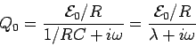
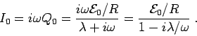
Now, the charge on a capacitor cannot be measured directly;
what we usually want to know is the current
![]() . Since the entire time dependence of
. Since the entire time dependence of ![]() is in the factor
is in the factor
![]() , we have trivially
, we have trivially
Since everything we might want to know
(![]() ,
, ![]() and
and ![]() )
has the same time dependence
except for differences of phase
encoded in the complex amplitudes
)
has the same time dependence
except for differences of phase
encoded in the complex amplitudes ![]() and
and ![]() ,
we can think in terms of
an effective resistance
,
we can think in terms of
an effective resistance ![]() such that
such that
The current through the circuit
cannot be different in different places
(due to charge conservation)
and follows the time dependence of the driving voltage
but (because ![]() is generally complex)
is not generally in phase with it,
nor with the voltage drop across
is generally complex)
is not generally in phase with it,
nor with the voltage drop across ![]() :
:
From Eqs. (9) and (11)
one can easily deduce the phase differences
between these voltages at any time
(for example, ![]() )
when
)
when ![]() has its maximum negative real value:
the voltage drop across
has its maximum negative real value:
the voltage drop across ![]() will be real and positive
(it is always exactly out of phase with the driving voltage)
but the voltage drop across the capacitor will be
in the negative imaginary direction -
i.e. its real part will be zero at that instant.
will be real and positive
(it is always exactly out of phase with the driving voltage)
but the voltage drop across the capacitor will be
in the negative imaginary direction -
i.e. its real part will be zero at that instant.
A convenient way of looking at this is with the "Phase Circle" shown in Fig. 21.2, where the "directions" of the voltage drops in "complex phase space" are shown as vectors. Both voltage drops "rotate" in this "phase space" at a constant frequency
![\begin{figure}~\\ [-0.5\baselineskip]
\begin{center}\mbox{\epsfig{file=PS/phase_circle_RC.ps,height=2.0in}}\end{center}
\end{figure}](img34.gif)