 |
 |
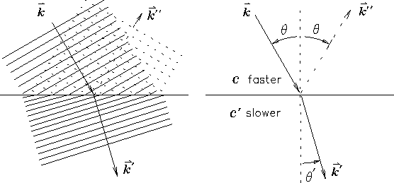
When a wave crosses a boundary between two regions in which its velocity of propagation has different values, it "bends" toward the region with the slower propagation velocity. The following mnemonic image can help you remember the qualitative sense of this phenomenon, which is known as REFRACTION: picture the wave front approaching the boundary as a yardstick moving through some fluid in a direction perpendicular to its length. If one end runs into a thicker fluid first, it will "drag" that end a little so that the trailing end gets ahead of it, changing the direction of motion gradually until the whole meter stick is in the thicker fluid where it will move more slowly.14.18
Conversely, if one end emerges first into a thinner
fluid (where it can move faster) it will pick up speed
and the trailing end will fall behind.
This picture also explains why there is no "bending"
if the wave hits the interface normally (at right angles).
The details are revealed mathematically (of course) in
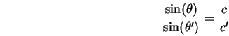
SNELL'S LAW:14.19
Another semi-obvious consequence of the fact that
the "crests" of the waves remain continuous14.20is that the wavelength gets shorter as the wave enters
the "thicker" medium or longer as it enters a "thinner"
medium. Another way of putting this is that
the frequency stays the same (and therefore so does
the period ![]() ) as the wave crosses the boundary.
Since
) as the wave crosses the boundary.
Since
![]() this means that
if the velocity decreases, so does the wavelength.
One can follow this argument a bit further to derive
SNELL'S LAW from a combination of geometry and logic.
I haven't done this, but you might want to . . . .
this means that
if the velocity decreases, so does the wavelength.
One can follow this argument a bit further to derive
SNELL'S LAW from a combination of geometry and logic.
I haven't done this, but you might want to . . . .
There is also always a reflected wave at any interface,
though it may be weak. The reflected wave is shown as dotted lines
in Figs. 14.10 and 14.11, where
its wavevector is denoted ![]() .
This phenomenon is familiar
as a source of annoyance to anyone who has tried to watch television
in a room with a sunny window facing the TV screen. However, it does
have some redeeming features, as can be deduced from a thoughtful
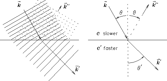
analysis of Eq. (42). For instance, if the wave is
emerging from a "thick" medium into a "thin" medium
as in Fig. 14.11
(like light emerging from glass into air), then there is
some incoming angle
.
This phenomenon is familiar
as a source of annoyance to anyone who has tried to watch television
in a room with a sunny window facing the TV screen. However, it does
have some redeeming features, as can be deduced from a thoughtful
analysis of Eq. (42). For instance, if the wave is
emerging from a "thick" medium into a "thin" medium
as in Fig. 14.11
(like light emerging from glass into air), then there is
some incoming angle ![]() , called the CRITICAL ANGLE,
for which the refracted wave will actually be
parallel to the interface - i.e.
, called the CRITICAL ANGLE,
for which the refracted wave will actually be
parallel to the interface - i.e.
![]() (90
(90![]() ). This implies
). This implies
![]() so that
SNELL'S LAW reads
so that
SNELL'S LAW reads
What happens, qualitatively, is that as ![]() gets larger and
larger (closer and closer to "grazing incidence")
the amplitude (strength) of the transmitted wave gets
weaker and weaker, while the amplitude of the reflected
wave gets stronger and stronger, until for incoming angles
gets larger and
larger (closer and closer to "grazing incidence")
the amplitude (strength) of the transmitted wave gets
weaker and weaker, while the amplitude of the reflected
wave gets stronger and stronger, until for incoming angles
![]() there is no transmitted wave
and the wave is entirely reflected. This phenomenon
is known as TOTAL INTERNAL REFLECTION and has quite a
few practical consequences.
there is no transmitted wave
and the wave is entirely reflected. This phenomenon
is known as TOTAL INTERNAL REFLECTION and has quite a
few practical consequences.
Because of total internal reflection, a fish cannot
see out of the water except for a limited "cone" of vision
overhead bounded by the critical angle for water,
which is about
![]() or 49
or 49![]() .
Lest this lend
reckless abandon to fishermen, it should be kept in mind
that the light "rays" which appear to come from just under
49
.
Lest this lend
reckless abandon to fishermen, it should be kept in mind
that the light "rays" which appear to come from just under
49![]() from the vertical are actually coming from just
across the water's surface, so the fish has a pretty good view
of the surrounding environment - it just looks a bit distorted.
To observe this phenomenon with your own eyes, put on a good
diving mask, carefully slip into a still pool and hold your breath
until the surface is perfectly calm again. Looking up at the
surface, you will see the world from the fish's perspective
(except that the fish is probably a good deal less anoxic) -
inside a cone of about 49
from the vertical are actually coming from just
across the water's surface, so the fish has a pretty good view
of the surrounding environment - it just looks a bit distorted.
To observe this phenomenon with your own eyes, put on a good
diving mask, carefully slip into a still pool and hold your breath
until the surface is perfectly calm again. Looking up at the
surface, you will see the world from the fish's perspective
(except that the fish is probably a good deal less anoxic) -
inside a cone of about 49![]() from the vertical,
you can see out of the water; but outside that cone,
the surface forms a perfect mirror!
from the vertical,
you can see out of the water; but outside that cone,
the surface forms a perfect mirror!
How total is total internal reflection? Total! If the surface has no scratches etc., the light is perfectly reflected back into the denser medium. This is how "light pipes" work - light put into one end of a long Lucite rod will follow the rod through bends and twists (as long as they are "gentle" so that the light never hits the surface at less than the critical angle) and emerge at the other end attenuated only by the absorption in the Lucite itself. Even better transmission is achieved in FIBER OPTICS, where fine threads of special glass are prepared with extremely low absorption for the wavelengths of light that are used to send signals down them. A faint pulse of light sent into one end of a fiber optic transmission line will emerge many kilometers down the line with nothing "leaking out" in between. (This feature is especially attractive to those who don't want their conversations bugged, or so I am told.) Another application was invented by Lorne Whitehead while he was a UBC Physics graduate student: by an ingenious trick he was able to make a large-diameter hollow LIGHT PIPE [trademark] which avoids even the small losses in the Lucite itself! Using this trick he is able to "pipe" large amounts of light from single (efficient) light sources [including rooftop solar collectors] into other areas [like the interiors of office buildings] using strictly passive components that do not wear out. He founded a company called TIR - see if you can guess what the acronym stands for!